SmartSDR™ for iOS – Tools
1.Tools
 Each Icon represents a separate Tool. Some Tools need to be unlocked (purchased) before they can be used as described in the Main Manual from Chapter 2.2 onward.
1.1.FlexRadio
The main purpose of this Tool is to enable (unlock) the possibility to connect to your FlexRadio device as explained in the main Manual in Chapter 2.2
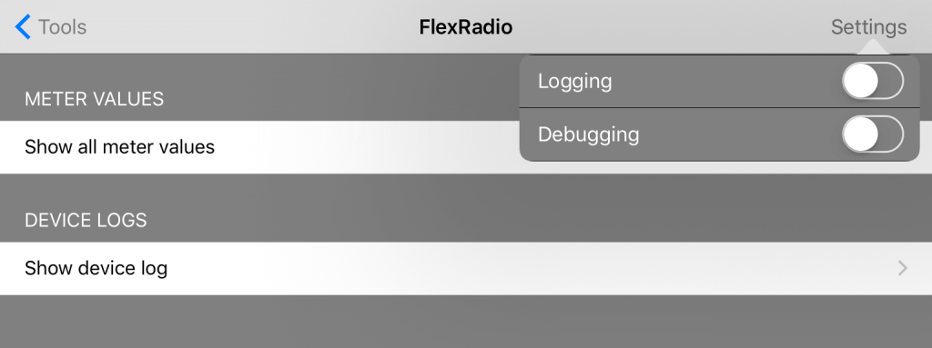
In addition, this tool offers two features that help to identify issues with or along with your FlexRadio.
The Show all meter values section provides values of all meters of your FlexRadio, not only those meters displayed in the main screen of this App but also Voltages, Power and Temperature value.
If turned on, the App will also log additional information which can be viewed and cleared using the Show device log menu.
1.2.Band Plan
The Band Plan tool provides a frequency overview of all HF HAM Bands for your particular region as well as the modes and maximum bandwidth as suggested by the IARU.
Please note: You need to select your particular IARU region in the General Settings in order to see the correct Band Plan for your region.
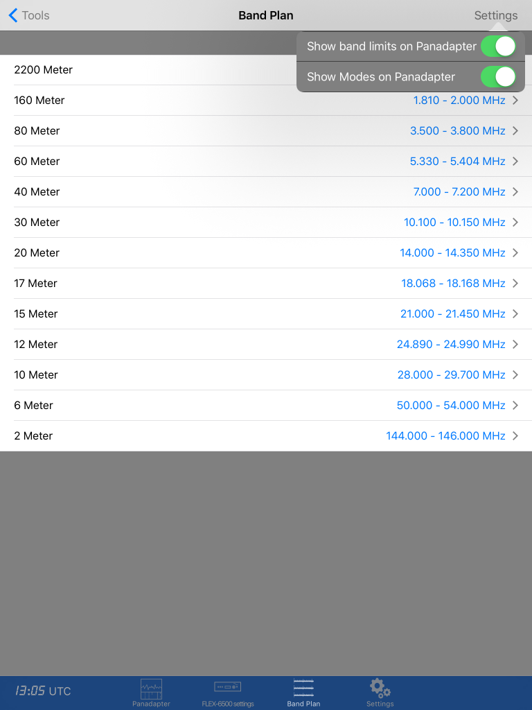
The Setting menu at the top allows you to select, whether or not, the Band limits and modes should be visible within the Panadapter as seen below:
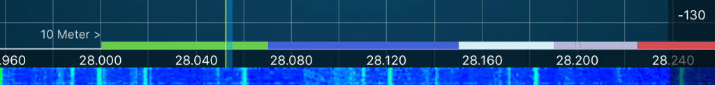
The “10 Meter >” information represents the Band limits information and the colored line represent the various modes like CW (green), Digimodes (blue), Narrow modes (Cyan), All modes (red), Satellite (yellow), others such as Beacons or guard channels (gray).
Inside the Band Plan tool, you can tap on a Band in order to see the details.
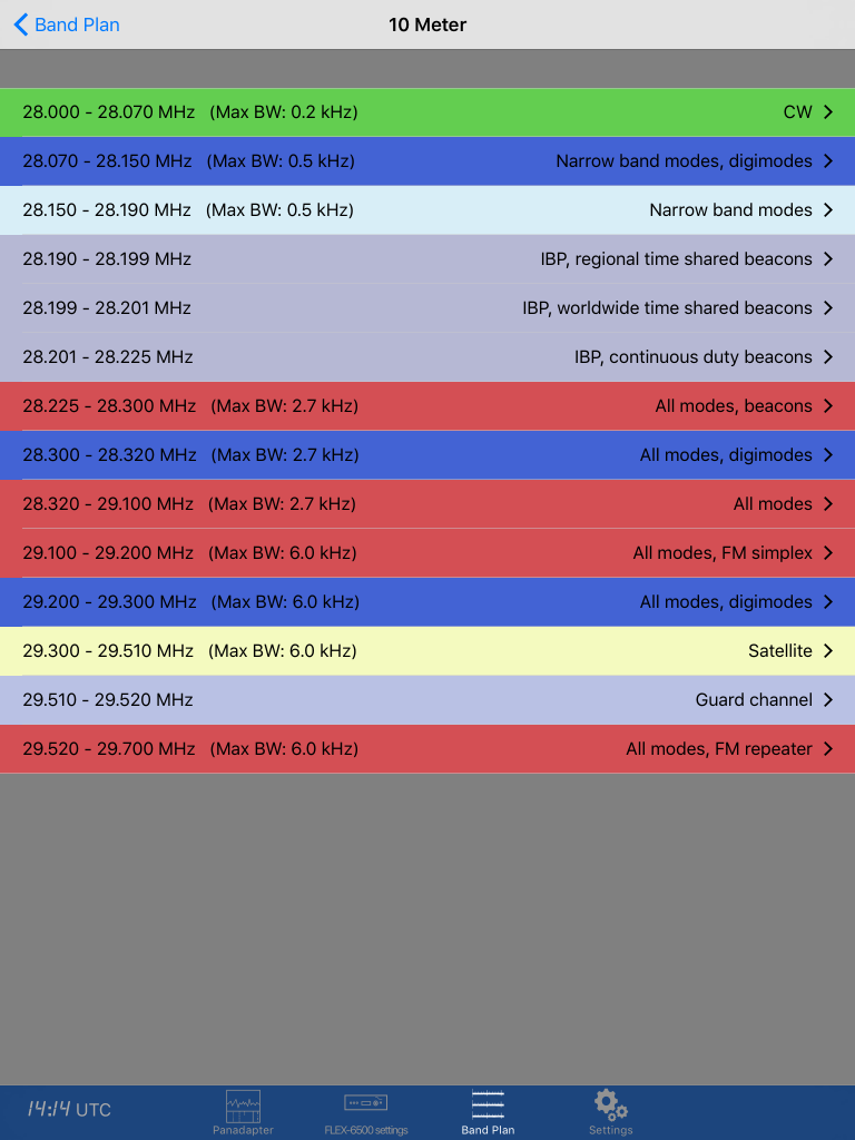
Modes will be displayed in the same colors as described above. From here, you can further tap on a mode (e.g. CW) which will switch to the Panadapter and automatically adjusts the visible Bandwidth accordingly.
1.3.DX-Cluster
The DX-Cluster Tool connects to any of several pre-defined worldwide DX-Cluster Databases or even your local CW-Skimmer and displays results (Spots) directly on the Panadapter or let’s you directly jump to the frequency of a particular Spot by just tapping on an entry in the list.
To start DX-Cluster querying, you need to hit the Icon in the top right hand corner first. The query will be repeated automatically in the given interval.
Tapping once on a line in the list will open a detail screen with details about the Call and Spotter. From here it is also possible to perform a HamQTH or QRZ.com lookup. For this, you need to enter your corresponding HamQTH and QRZ.com credentials on the Settings screen of this App.
Tapping twice on a line will jump to the panadapter and tune the current Slice to the frequency.
To search the list for a particular call, just hit the Spyglass icon in the lower right corner and enter your search term. This can be a call you want to search for. You can also enter itu= or cq= followed by a ITU-Zone or CQ-Zone to search for Calls from that particular ITU or CQ Zone.
Tap Filter in the bottom line to open the filter settings. Here you can select which Bands or modes you like to see – or you don’t like to see – in the list.
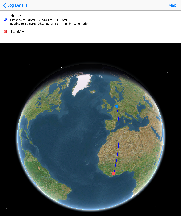
MAPS
You can display the whole list on a Map (Globe) or individual Spots from the Spot Detail screen. In this case, you will also get information about the distance between your QTH and the Call as well as bearing in degree.
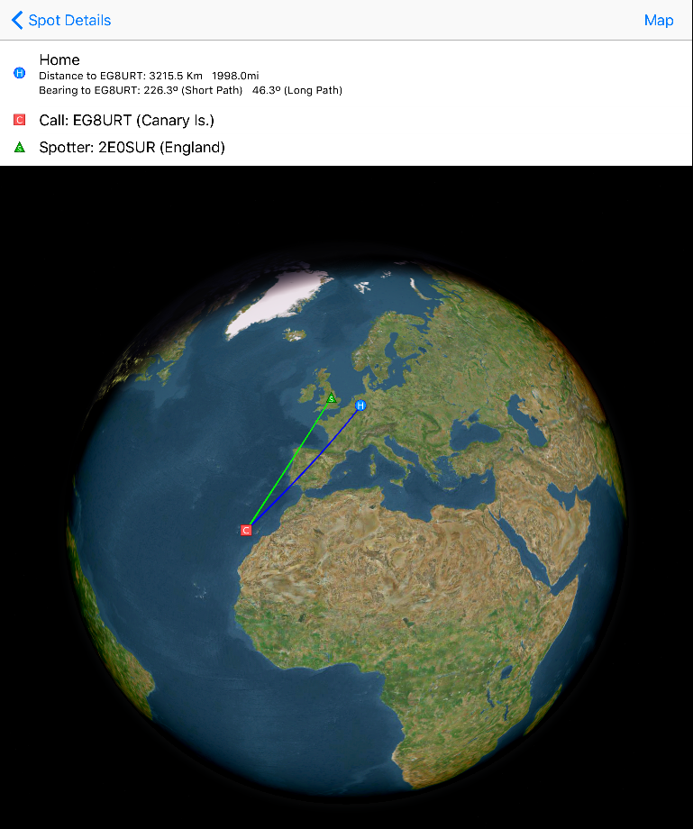
For gray line DX, you can also see sunup and sundown on this Globe.
Please note: For the Bearing and Distance calculation and to draw the blue line between your QTH and the Call, you will need to enter your Home QTH grid location on the Settings screen of the App (please only use four digits here e.g. JO31)
SETTINGS
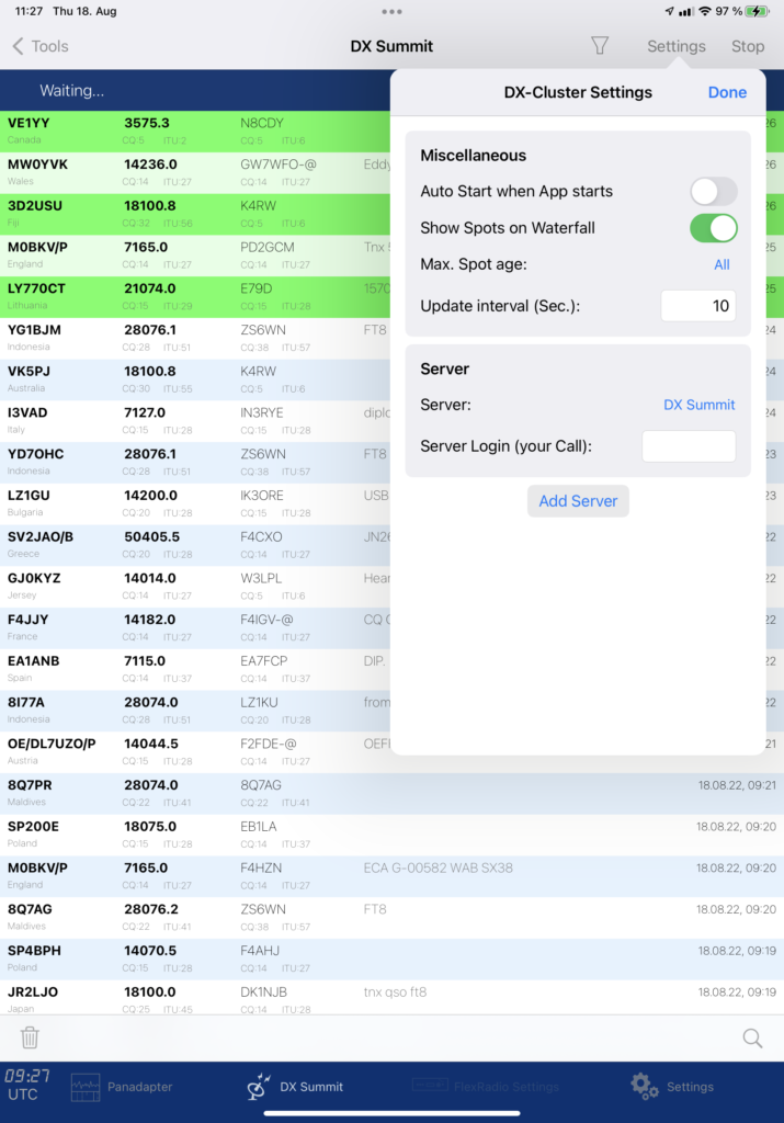
There are various Settings available in the DX-Cluster Tool.
With Show Spots on Panadapter you can choose whether or not to see all spots not only in the List but also on the Panadapter like shown below:
Please note, you can tap on any of the Spots displayed in the Panadapter to tune the currently active Slice to that frequency.
The setting Autostart will cause the DX-Cluster Tool to automatically start to connect and query the DX-Cluster Server once the App has been started.
The Max. Spot age setting define, how long Spots should be displayed. Spots older than the selected time will then no longer be displayed. This is useful as the HAM might have switched the frequency or discontinued meanwhile.
Update interval defines how often (in seconds) the DX-Cluster database should be queried.
Server lets you select one of the predefined servers or let you enter your own DX-Cluster (e.g. Skimmer) Server.
Some of the predefined server or even your own Server may require a login by entering your Call sign. For this, you can enter Your Call sign under Server Login (your call).
When selecting Server, you will see a list of predefined servers. Just tap on the desired entry and a check-mark will indicate your selection. You will have to press the start button (top right) again after selecting a different server.
Custom DX-Cluster Server
To add your own Server, press the + button at the top (or the Wastebasket to delete it). On the following screen you will need to provide a Title and necessary parameters of your Server. These parameters depend on the Software you are running and may be found in the Manual or Settings of the Software or the administrator of the DX-Cluster server you like to add.
Unfortunately, there is no real standard for DX-Cluster Servers. You may need to experiment with the type whether Standard Skimmer or Standard Telnet will work. Some Server also require some initial commands in order to generate DX-Cluster spots. You can enter this command in the corresponding entry field on the “Edit Settings” screen.
Some servers like DB0SUE for instance also require the submission of the your Callsign immediately after connection (before providing the usual information). For this, you can also use the initial command field and enter your call here (or the term {CALL} which will be replaced by the Call you entered on the main DX-Cluster settings screen) to provide this information to the Server right after the connection.
Debugging
If you run into any issues using your preferred or own DX-Cluster I suggest to first try a connection to the server with a standard Telnet program such as Putty or any other Telnet client. You can try to connect to the server address using the corresponding port to see if the connection to your server works in general. This way, you will also see if and what kind of information your server asks for, after connecting.
Next, open the FlexRadio Tool and enable logging in the Settings menu in the top right corner (Debugging can be left off).
Next, you can enter the same information (Address, Port) you have successfully tried before with your Telnet client in the Custom Server settings. Now try to connect to your server. If it doesn’t work, head back to the FlexRadio Tool and tap on “Show device log”. You can now inspect the communication between the App and your custom DX-Cluster server and may find some reasons for the issue and clues how to fix this.
PLEASE NOTE: Don’t forget to turn logging back off as this decreases the overall performance of the App.
1.4.Griffin PowerMate
This Tool allows to configure and use the so called “Griffin PowerMate Multi-Media Control Knob with Bluetooth Connectivity” for controlling the FlexRadio.
Please Note: Only the the Bluetooth LE variant of the PowerMate is supported. Not the USB variant.
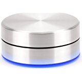
This Controller has no cable and will be connected via Bluetooth LE to your iPhone or iPad.
Please don’t forget to turn Bluetooth on before using the PowerMate.
This Controller has one Wheel, one Button (pressing the Wheel) and an LED. All three can be configured individually by using the “Edit Mapping” function, but to get started, first select “PowerMate default” as Mapping.
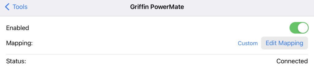
Now, you can switch “Enabled” on. The first time, you may get the message “Turn on Bluetooth to Allow “SmartSDR” to connect to your Accessories”.
Next, under Status, you will see “Connecting…“. Now, you need to tap once on your PowerMate and the Status should change from “Connecting…” to “Connected”.
With the “PowerMate default” Mapping, the PowerMate is configured to to use the Wheel for tuning the Active Slice frequency and the Button will toggle TX. The LED will indicate the MOX status.
To alter this default Mapping, just tap on “Edit Mapping” and the Mapping Editor will be opened. The Mapping editor is explained in Chapter “Mapping Editor“.
Once you changed the Mapping by using the Mapping Editor, the Mapping Entry on this screen will change from “PowerMate default” to “Custom“. By selecting “PowerMate default” again, you can revert back to the default mapping.
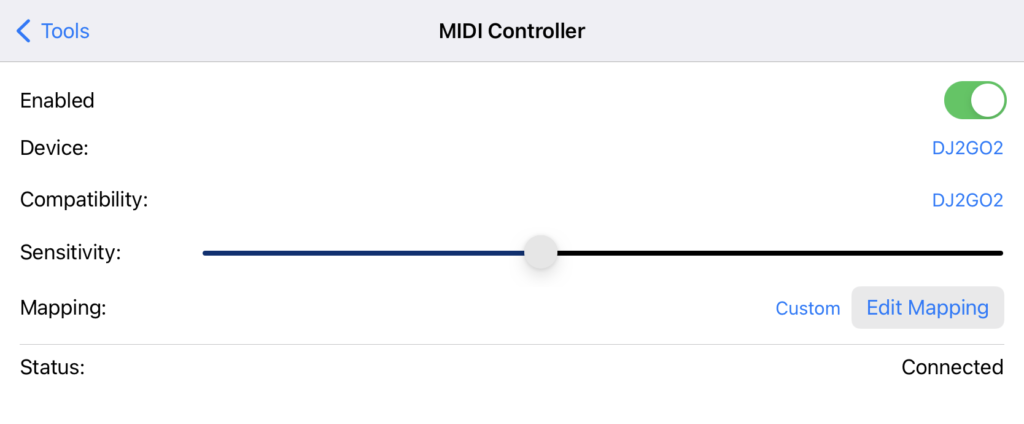
1.5.MIDI Controller
This Tool allows the configuration and use of the so called MIDI Controllers such as the “Behringer CMD Micro MIDI Controller” for use with the Radio.
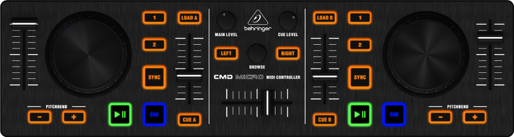
In addition to the CMD Micro, the following controller are also supported:
- Behringer CMD PL-1
- Hercules DJ Controller Compact
- Numark DJ2GO2
Other controllers may work as well but they are not tested.
Such a MIDI Controller needs to beconnected to your iPhone or iPad using a standard USB MIDI Connection.
The easiest and approved way to connect a MIDI Controller to your iPhone or iPad is by using Apples Standard Lightning USB 3.0 Camera Connection kit.
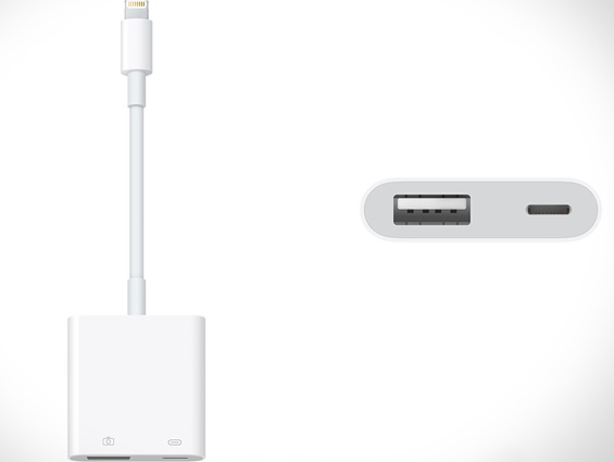
The Lightning plug needs to be connected to your iPhone or iPad, the USB Cable of your Behringer CMD Micro needs to be connected to this Adapter. For this solution, it is important to connect a Lightning Power source into the Lightning Socket of this Adapter. This is important because some MIDI Controllers will also be powered by this connection.
In some cases, you may see the message that “The connected USB Device cannot be used due to high power consumption”. In that case, please try another power Supply. The original Apple power supply that came along with your iPhone/iPad should work.
For Apple devices with USB-C connector like the iPad Pro, you can also connect the MIDI controller directly or using a USB to USB-C adapter.
There are also Wireless Bluetooth MIDI Adapters available which may work. I have tested some successfully which unfortunately disappeared from the Market afterwards. Keep in mind that these Bluetooth Adapters may also need to be powered.
Once you have everything attached as described before and once you unlocked this Tool, you can configure the controller connection.
First, you need to select your MIDI Device. Once you tap on “MIDI Device” you should see “CMD Micro” in the displayed list and just need to tap on this entry. If you don’t see the CMD Micro in that list, please check your Cable connections and the power supply as explained before.
The CMD Micro has three Wheels, five sliders, two Level controls, 20 Buttons and six LEDs. Everything can be configured individually by using the “Edit Mapping” function, but to get started, first select “CMD Micro default” as “Mapping“.
If you then switch on “Enabled” the Status should change to “Connected“.
With the “CMD Micro default” Mapping, you can now use the left Wheel to tune the Slice A frequency whereas the right Wheel will control Slice B frequency. Buttons and Sliders are also assigned to different FlexRadio settings.
To alter this default Mapping, just tap on “Edit Mapping” and the Mapping Editor will be opened. The Mapping editor is explained in Chapter “Mapping Editor” in the Appendix of this Manual.
Once you changed the Mapping by using the Mapping Editor, the Mapping Entry on this screen will change from “CMD Micro default ” to “Custom“. By selecting ” CMD Micro default” again, you can revert back to the default mapping.
1.6.Logbook
The Logbook has been implemented with the idea in mind that you will keep using your main PC, Mac or Web based logging Program for general Log-Maintenance, Awards and QSLs, eQSL.cc, LOTW Submissions etc.
This internal App logging feature should be an easy, quick and convenient solution for entering Logs while working with the App for later submission to your main Logging Software. For this, it supports ADIF Im- and Export. It also Synchronizes Logs across multiple iPhones/iPads via iCloud Drive.
Limited Contest support is also included (assuming you will rather use SmartSDR for Windows for your contests).
The Logbook also helps to complete the Log Entries by integrating HamQTH and QRZ.com lookups. Also, an internal Call sign Prefix database is included to identify DXCC, CQ-Zone, ITU-Zone etc. based on the Call Prefix.
It can also display all or individual Logs on a Map (Globe).
LOGBOOK SETTINGS
Before using the Logbook, please double check the Settings inside the Logbook Tool.
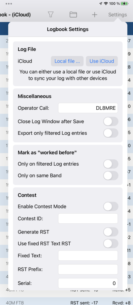
By hitting the “Use iCloud” button, the App uses a logbook which is synchronized with other devices via iCloud. This is the default setting.
To use a separate local file, just hit the “Local File…” button and create another file. You can switch between local files and iCloud logging at any time. To transfer a log from one to another, just use the ADIF export and import feature.
If “Use iCloud to sync Logbook” is set to On, your Logbook will be available and Synchronized with all other devices you may have which is using the same Apple ID. To use this feature, iCloud Drive needs to be enabled on your device. For further details, see the separate Chapter iCloud Drive in the Appendix of the manual.
For “Operator Call sign“, you can enter your Call or the Call which should be used as OPERATOR in the Log. (Please the content of the STATION of the Log is the Call you have entered under “My Call” in the main Settings of the App).
“Close Log Window after Save” means that the small logging window will be closed if you tap on Save. Otherwise it will remain visible on the Screen.
“Export only filtered Log entries” will only keep those entries that are currently visible and which are not filtered out in the ADIF export file.
“Contest Mode” means that you can use Serial Numbers to be counted upwards whenever you save a Log entry. Once selected, you can enter the official ADIF “Contest ID” for the particular Contest and for the RST generation, you can enter a Prefix and Suffix which will be put before and after the Serial number and the current Serial Number Value. Alternatively, you can also enter a “Fixed RST Text” if you don’t want to use a counting Serial.
If not in Contest Mode, RST Sent and Received will automatically filled with 599 or 59 (depending of the Mode).
LOGGING A CALL
To log a new Call, you have the following options:
- Tap on + at the top of the Loogbook Tool Screen
While on the Panadapter you can:
- Open the left Menu and tap on Log
- Use the View menu and select Log new QSO
- Double tap with two fingers on the Panadapter
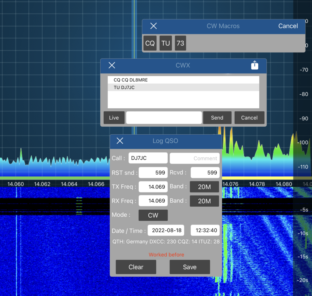
After this, a screen like this will be displayed:
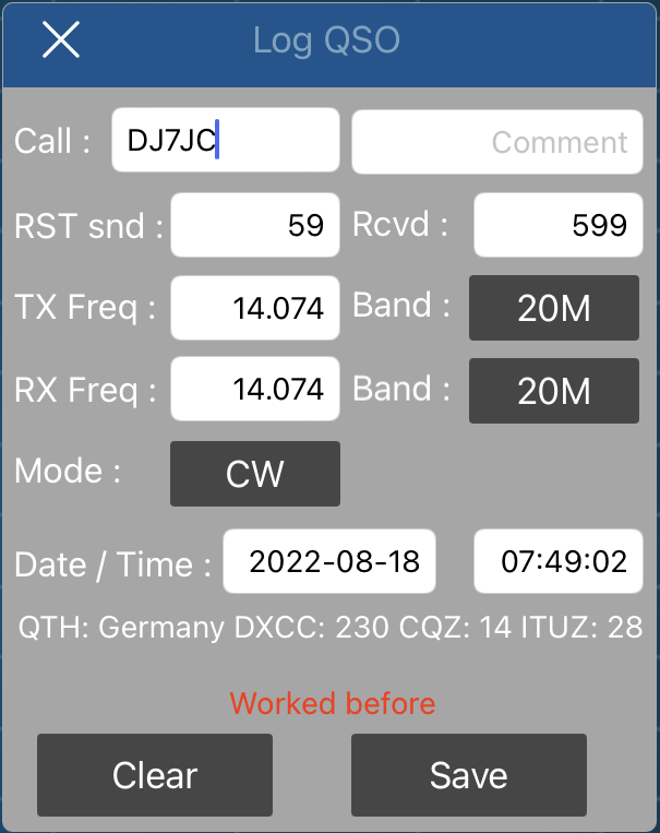
Fields like RST, Frequency, Band, Mode and Date/Time will be pre-filled depending on the Active and TX Slices.
After entering the Call, this screen will show the corresponding DXCC, CQ-Zone, ITU-Zone and Country of that call at the bottom.
ALTERING / COMPLETEING LOG ENTRIES
Back on the main Tool Logbook Screen, you can change the Sorting of the list or search for a particular Call or Comment by using the buttons at bottom of the screen.
You can tap each entry to alter or complete a log in the Log-Details screen as shown below:
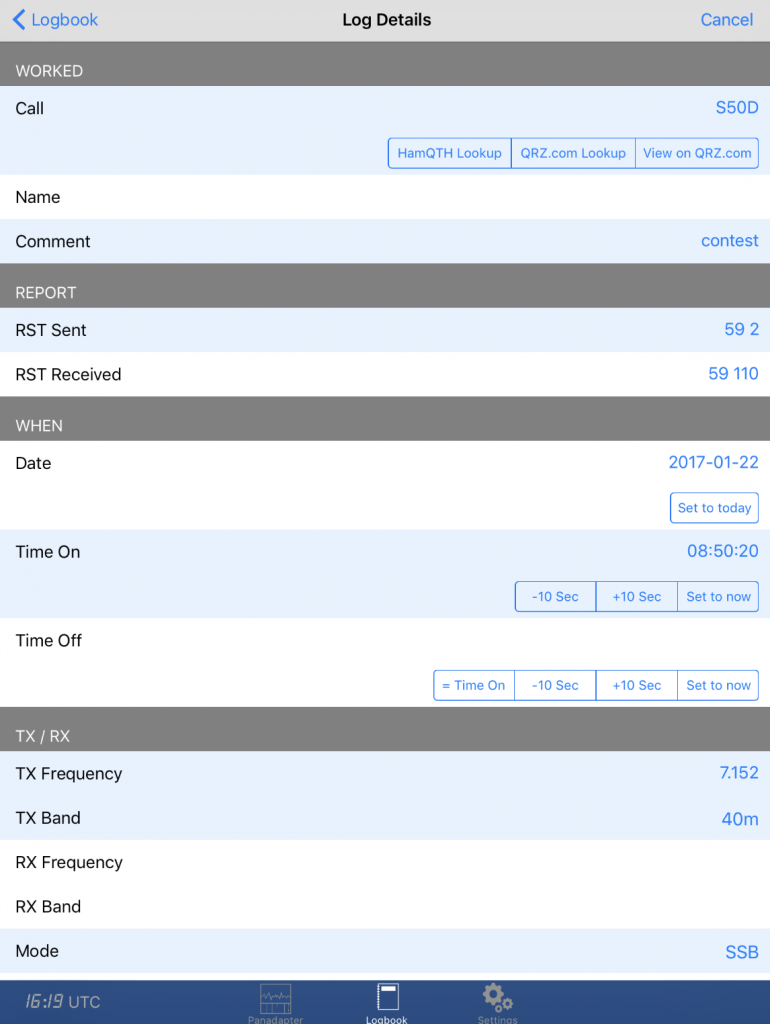
From here, you can adjust the Time On and Off times and all other Logbook fields as well as additional fields, not available on the small log entry screen.
By tapping on HamQTH or QRZ.com Lookup, you will see a list of information available for the particular call. By tapping on “Use this information” this data will be copied to your Log entry.
Please note: For using HamQTH and/or QRZ.com you need an account on each platform. For QRZ.com, in addition, you need an active XML Logbook data subscription (see https://ssl.qrz.com/products/index.html). The Credentials need to be entered in the main settings of the App.
“View on QRZ.com” can be used even without an active QRZ.com account. However, here, only the usual QRZ.com website (for the particular Call) with Ads will be displayed.
If the location information is available for a Call, you will see a Map button which will show the location of the Call and your QTH on the map and calculates the distance and bearing to the call.
CWX MACROS
Log entries can be used in CWX Macros. The following N1MM compatible Macros are supported:
{CALL}, {LOG}, {SENTRST}, {COMMENT}, {MYCALL}, {TXFREQ}, {RXFREQ}, {TXBAND}, {RXBAND}, {DATE}, {TIME}
When using these Macros in CWX Macros, the text will be replaced by text of the corresponding Log entry. For instance {CALL} will be replaced by the currently entered Call.
The {LOG] Macro will save the current Log and prepares to enter a new entry.
IMPORT / EXPORT
By using the Folder Icon at the top of the Logbook screen, you can Export and Import ADIF Files.
It is possible to Import or Export files via Email or iCloud Drive.
If you select Email, an Email will be generated which includes the ADIF File as attachment. For the opposite Direction, to import an ADIF File via Email, you just need to open the Mail App, open the Inbox with your Mail that contains the ADIF file, next just tap on the file attachment (the ADIF File). Then you will see an App selection of Apps that can be used to open this file. Selecting SmartSDR will open SmartSDR and import the File.
A more convenient Option to Im- and Export ADIF Files is to use iCloud Drive. (For details about iCloud Drive, please see the separate Chapter iCloud Drive in the Appendix of this Manual.)
PLEASE NOTE: All ADIF Files needs to have the extension .adi (e.g. mylog.adi).
After importing a file, you will be asked if you like to “Append” or “Replace” the imported Log to your current Log. If you select “Append”, the content of the file will be appended to the list. If you select “Replace”, your existing Log will be cleared before the file will be imported.
When importing ADIF Files from another Log Program, you may see the message “The File contains Log Entries with non-standard Fields”. This means, that the Log Program has stored additional proprietary information to the Log File which cannot be used or interpreted by this App. It is safe to import such a Log file to this App but keep in mind that the proprietary information will not be available when exporting logs back to that Program.
1.7.Flic
The Flic tool adds support for the so called Flic Smart Bluetooth Buttons (More information can be found here).
You can add as many buttons you like and can assign various Radio functions like PTT, Tune, Mute, CWX Macros for press and release, double click or hold.
After unlocking this tool and purchasing a Button, you need to register an account on flick.io and need to install the flick iOS App from the AppStore. Next Add your new Flic Button to the Flic App. If you have more than one Button, it is recommended to assign names for the Buttons (please see the Flic Manual for details).
No further action is required on the Flic App. You don’t have to assign actions from inside the Flic App unless you want to use the Button for other purposes than for SmartSDR for iOS.
Next, open the Flic tool of SmartSDR for iOS and switch on the Enabled setting.
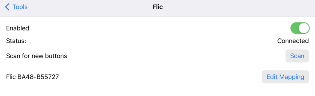
Now, when pressing a Flic button (the physical button), the Button ID will appear in the list. You can also use the Scan button to add a new, unregistered Flic button.
Next, you can decide what should happen, when using the button. For this, tap on Edit Mapping.
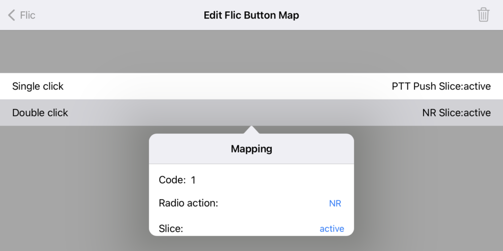
On this screen, you can assign Button mappings for the three Button options:
- Single click (which has an Up and Down state)
- Double click
- Long press
Please note that Double click and Long press will also always generate a Single click so in most cases, where you want to assign functions for Double click or long press, it makes no sense to also assign functions to single click.
If you want to remove an assignment, you can swipe the line left or just select “Not assigned”.
To delete the whole button, just tap on the wastebasket at the top of the screen.
Details about the possible Mappings can be found in chapter “Mapping Editor“.
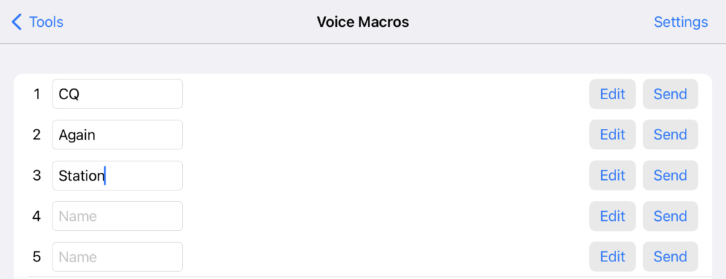
1.8.Voice Macros
The Voice Macro feature allows to record voice using your iPhone / iPad built in microphone or connected headset. Such voice macros can be played back later on while in QSOs.
This feature works similar to the CWX Macro feature but plays back audio while in phone mode (SSB, AM or FM).
RECORDING A VOICE MACRO
To record a Voice Macro, open the Voice Macro Tool and tap on Edit on one of the 12 available Macros.
Next, tap on Record on the Recording Editing screen
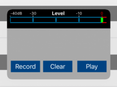
While recording, watch the level meter at the top.
Next, you can tap Play to test your recording or Record to start over again.
When tapping on Settings in the upper right corner of the Voice Macro screen, you can change various settings:
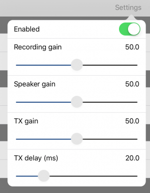
Enable will show or hide the Function Keys on the Panadapter (see further below).
Recording gain can be used to adjust the microphone volume.
Speaker gain can be used to adjust the playback volume on your local device. If you don’t want to hear your recording while transmitting, just turn this slider completely to the left.
TX gain represents the transmitting volume.
TX delay can be used to add a delay after PTT keying, before the voice macro starts to play.
Please note: For best results, use an external microphone (headset) and try to find the right balance between the Recording (Microphone) gain and TX gain.
PLAYBACK A VOICE MACRO
Once you have recorded a Voice Macro and the feature has been enabled in the Voice Macro settings, you can send your voice Macro over the air from the Panadapter view by showing the Macros Panel. For this, ensure you are in a phone mode (AM,FM,SSB) and use the View menu and select Macros Panel.
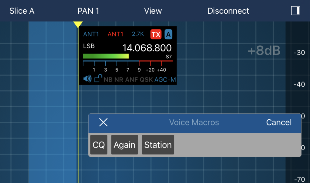
Tapping on one of the entries will submit your Voice Macro.
Tapping on Cancel will suspend the transmission.
This function is not available in CW mode (active TX slice set to CW).
1.9.CW Macros
For CW, you can maintain Macros with individual messages which can be sent from the Macros Panel from the Panadapter.
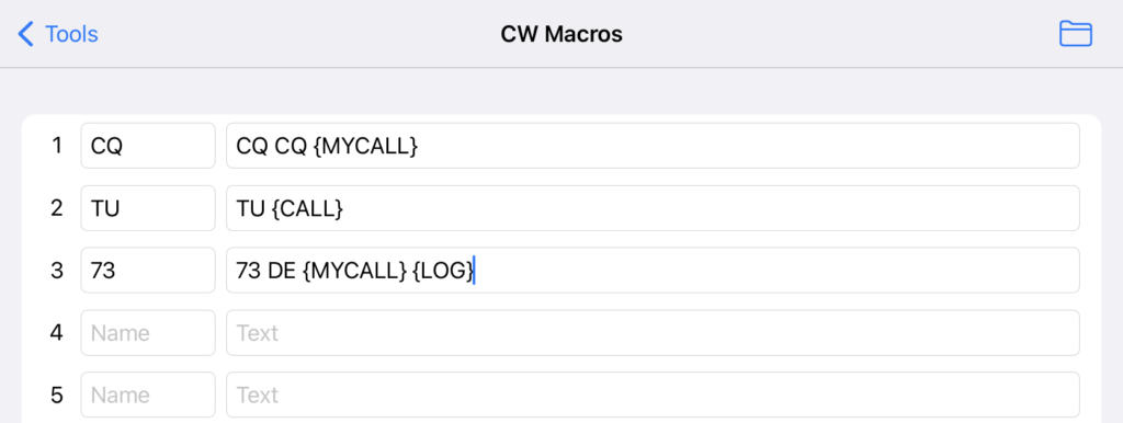
Macros can use variables such as {CALL} which will be replaced before the message will be sent. The {CALL} Macro will be replaced by the Call which has already been entered in the Log Window. The App supports the following N1MM compatible Macros: {CALL}, {LOG}, {SENTRST}, {COMMENT}, {MYCALL}, {TXFREQ}, {RXFREQ}, {TXBAND}, {RXBAND}, {DATE}, {TIME}.
To submit a Macro, ensure you are in CW mode and display the Macros Panel from the View menu.
1.10.Network Stats
This Tool displays Network Statistics, useful to identify network issues.
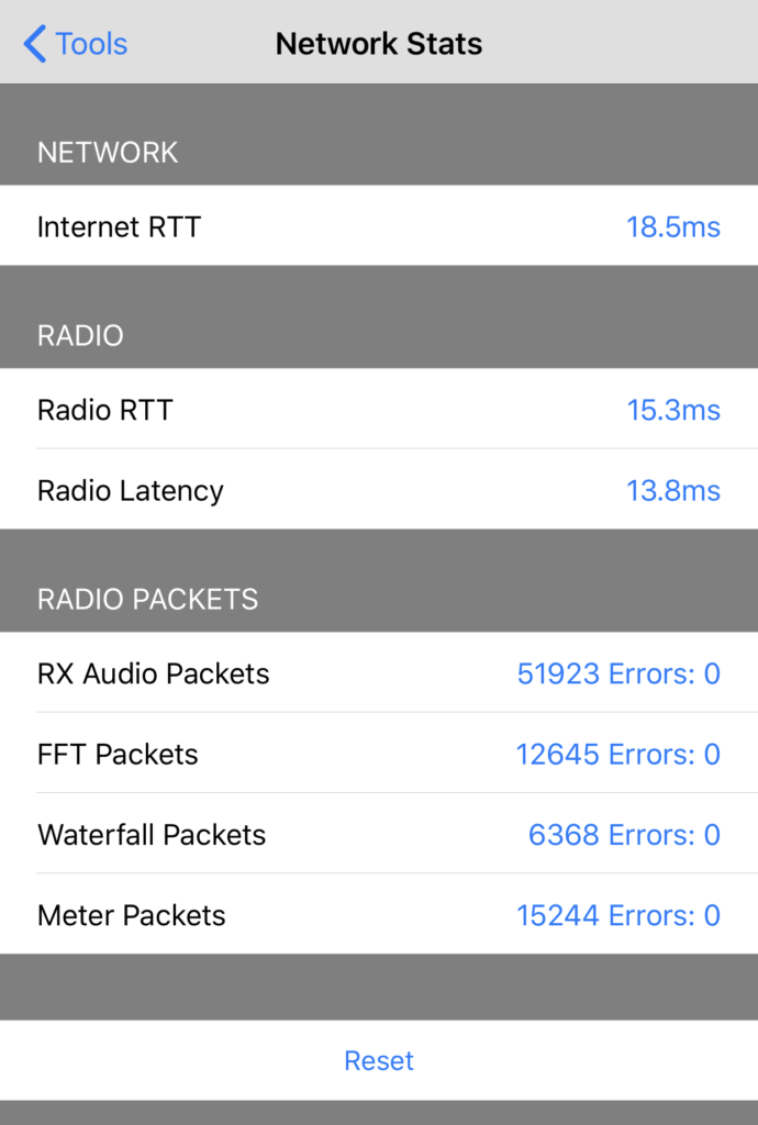
Internet RTT is the Rount-Trip-Time (the time to the server and back) to a server on the Internet. This value should be lower than 20 ms on local (WiFi only) connections and 100 ms on Cellular connections.
Higher values indicate general issues with your network connection.
Radio RTT is the Round-Trip-Time to your Radio. These should also be between 20 ms local or 100 ms on Cellular connections. However, this value should always be lower or at least equal than the Internet RTT. If this value is significantly higher (e.g. 1.5 or twice as high as your Internet RTT) there are issues with your local network (e.g. wrong LAN Cables or wrong FullDuplex/FalfDuplex network settings etc.)
The Radio Latency is the time your Radio answers to Commands. This value should be similar to the Radio RTT. If this value is significantly higher (e.g. 1.5 or twice as high as your Radio RTT) your Radio is responding very slow and you may want to try to Power Cycle your Radio.
The Radio Packets section at the bottom shows the number of packets received for certain packet types along with the Error count and percentage.
If the number of Packets remains zero even after you are connected (and even when there are reasonable RTT and Latency values), there will be issues with the Radio UDP communication.
A certain Error percentage (1-5%) is normal and usually covered by the automatic error correction and often not even noticeable. Errors may even temporary happen if the device is too busy (e.g. while temporary switching to another App). However, continuous Errors might be an indication of network issues (either Cell when using SmartLink or and/or on your local network).
The Reset button at the top can be used to set the error counter to zero which is useful to see if there are any changes after changing some settings.
In case of Network issues, please consult the “Common issues” section in the SmartSDR for iOS Manual.
1.11.HomeKit
This App now supports HomeKit to control peripherals in your Shack such as Antenna Switches, PAs or even power up FlexRadio remotely.
There is already a wide range of different HomeKit devices (so called accessories) available. All accessories that can either be switched, powered-on or even dimmed are supported by this App. For instance, you can use a HomeKit compatible power outlet for switching your FlexRadio on and off.
More about HomeKit can be found on Apples HomeKit website.
Before using HomeKit accessories from inside the App, they need to be registered and available from Apple’s HomeKit App.
The way how SmartSDR for iOS supports such HomeKit Accessories is to allow you to select the accessories you like to use from inside the App and then, SmartSDR for iOS offers a Home Icon at the top of the Panadapter screen which can be used to access these accessories conveniently to turn them on or off.
Given you already have HomeKit and your accessories readily setup, just start the HomeKit Tool of SmartSDR for iOS.
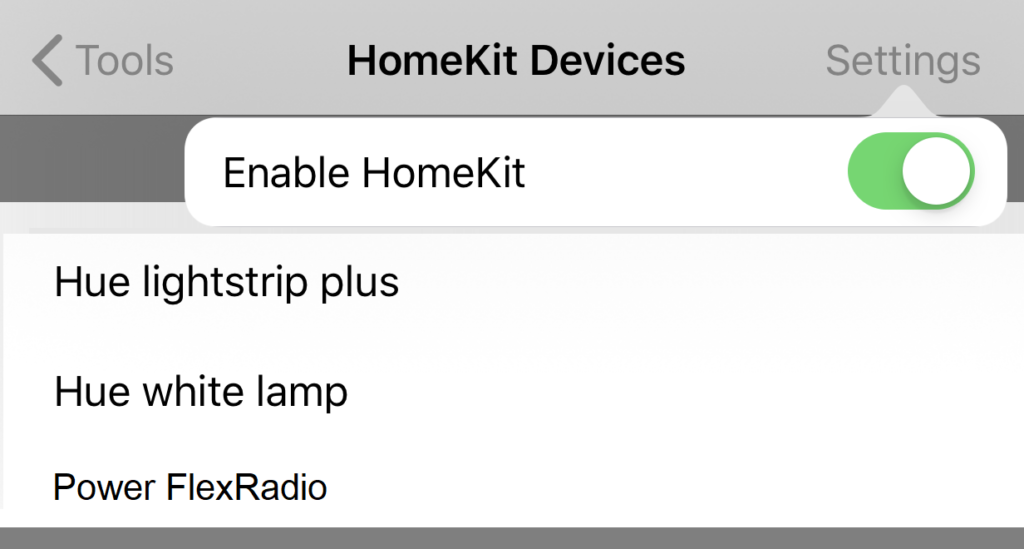
After selecting “Enable HomeKit” using the Settings menu at the top right corner, you should see all available HomeKit accessories in the list.
If that’s not the case immediately, just wait a few seconds or pull the list to refresh it.
Once you see the list, you just need to tap on the accessories you like to use from inside the App. A selected accessory will show a check-mark on the right side. Tapping again will remove the check-mark.
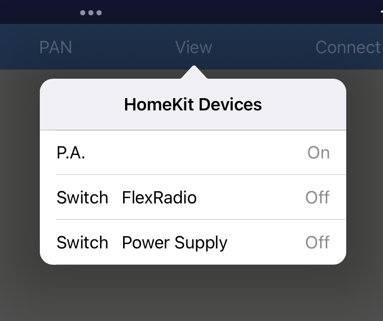
Once that’s done, you can jump to the Panadapter (lower left tab) and use the View → HomeKit Menu to show and toggle the selected HomeKit components.
Please note: SmartLink is not necessary for HomeKit. You can access any HomeKitdevice without previously connecting to your Radio via SmartLink (or VPN). This way, you can even power on your Radio before you can connect to it using SmartLink.
If connected via Cell, HomeKit may initially respond a bit slow for the first attempt. It may also show a wrong or undetermined status (on or off) of your accessory.
1.12.FT8
This tool allows to use and operate the popular FT8 and FT4 mode, invented by Nobel prize winner Joe Taylor, K1JT.
Foreword (please read)
I met Joe at the Dayton FlexRadio Banquet in 2019. His speech inspired me to add this feature to my App. It took me some time to understand his way of encoding and decoding the FT8 messages and I learned a lot about FFT (fast Fourier transformation) but now it’s done.
Thanks to all testers who provided valuable feedback and who helped to make this feature possible. But a special thanks to Joe Taylor who brought us this wonderful mode.
Requirements / Features
The FT8 tool doesn’t run on iPhones (except for the iPhone Max models) due to its limited screen size. It needs an iPad, iPhone XS Max or iPhone 11 Max with a larger screen. My tests even on older iPads show that it works but the faster the iPad, the better it is. The FT8 calculations are quite complex and time consuming. If they take too long, transmission will start late which may prevent others to decode your message.
Also, FlexRadio firmware Version 2.5 is a minimum required to run this FT8 tool.
So far, the App only supports FT4 and FT8. Also, no Contest or DX-Pedition mode is supported. It just supports standard QSO’s which are about 95% of all FT4 and FT8 QSOs.
The App supports AUTO mode to automatically generate answer messages based on received messages. It also supports Auto Logging and prompts to log a QSO with all entries pre-filled based on the recent QSO. Worked before Calls will be marked to prevent working them again. CQ Calls will also be displayed on the Panadapter just like DX-Cluster Spots.
How to use
My approach was to offer FT8 with minimal or no configuration and operation effort. If you are already familiar with WSJT-X, you will immediately know how to operate in FT8 with my App. If you have never worked FT8 before or found it too complicated, just read the following basics and you should be set.
My hope is, to encourage more HAMs to join this fantastic new way to get in contact with each other by providing a simple and easy to use FT8 tool. Even if you found FT8 too complicated in the past, just give it a try with this tool. No cable fiddling, audio interfaces, strange settings or CAT commands.
Just open this tool and start your first FT8 QSO.
A few FT8 Basics
A typical FT8 QSO starts by somebody (say K1CQ) calling CQ, next somebody like you (say DC1ME) is answering. Both will then exchange their signal reports and optionally end the QSO by saying 73.
Here is how it typically looks like:
| Caller | You | Meaning |
| CQ K1CQ EN61 | K1CQ is Calling CQ. His Grid locator is EN61 | |
| K1CQ DC1ME JO12 | You are replying to him with your Grid locator | |
| DC1ME K1CQ -11 | K1CQ responds to you with a signal report | |
| K1CQ DC1ME R-10 | You, confirming his report and send your own report |
Now, there are two typical options:
Option 1 (the fastest and more common):
| DC1ME K1CQ RR73 | K1CQ confirmed the reception of your report and says best regards. The QSO is done now. No need to respond again. |
Option 2 (more polite option which takes longer):
| DC1ME K1CQ RRR | K1CQ confirmed the reception of your report. | |
| K1CQ DC1ME 73 | You say best regards. | |
| DC1ME K1CQ 73 | K1CQ send his best regards and the QSO is done. |
If you would like to call CQ yourself instead, the procedure is the same. Just swap the Callsigns in the above table.
These so-called FT8 messages cannot be longer than 13 Characters. It takes 13 seconds to transfer these messages and they will be exchanged every 15 seconds. Thus, there can be 4 messages per minute. When sending at second zero or 30 it is called “even” or “first”. When sending at second 15 or 45, it is called “odd”.
Besides these aforementioned typical QSO messages, there is additional information that will be added to messages in Contests Mode or DXpedition mode. These modes are not supported by this FT8 tool.
CQ Callers may also add either DX or the desired destination to their CQ message if they just want to get an answer from certain stations.
For example:
| CQ DX K1CQ EN61 | K1CQ just wants to have DX QSOs |
| CQ JA K1CQ EN61 | K1CQ just want to have contact with Japan |
And that’s pretty much it. That’s all you need to know to operate in FT8 with this App.
If you want to learn more, just head to G4IFBs website which includes a fantastic FT8 Operating guide, written by Gary Hinson, ZL2IFB : www.g4ifb.com which is also available in other languages.
Using the FT8 tool
You can start the FT8 tool by tapping the corresponding Icon on the tools screen.
To start the FT8 mode, you will need to be connected to your Radio and to tap on the RX button in the upper left corner.
If you tap on the Frequency button next to the RX button, you can select the Band or Frequency you want to operate. These Frequencies are fixed and you should only operate on these predefined frequencies.
Please note: The frequencies may differ depending on your location so please ensure that you set the correct IARU Region for the location from where you want to operate.
Please also ensure that you did set your Callsign and your Grid (QTH) locator.
All of this can be entered under the App’s Settings screen (lower right Settings Icon).
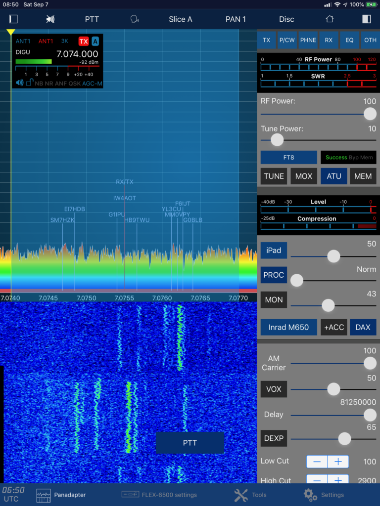
Once you hit RX, the Radio will not just tune to the right frequency. Also, all necessary parameters such as Mode, DAX, DAX Channel, Bandwidth etc.) will be set automatically.
After at least 15 seconds, you may see the first FT8 conversations in the upper receiving part of the screen.
The progress indicator at the top indicates the duration of an even (green) or odd (blue) reception phase. If you are transmitting, this indicator gets red.
Receiving
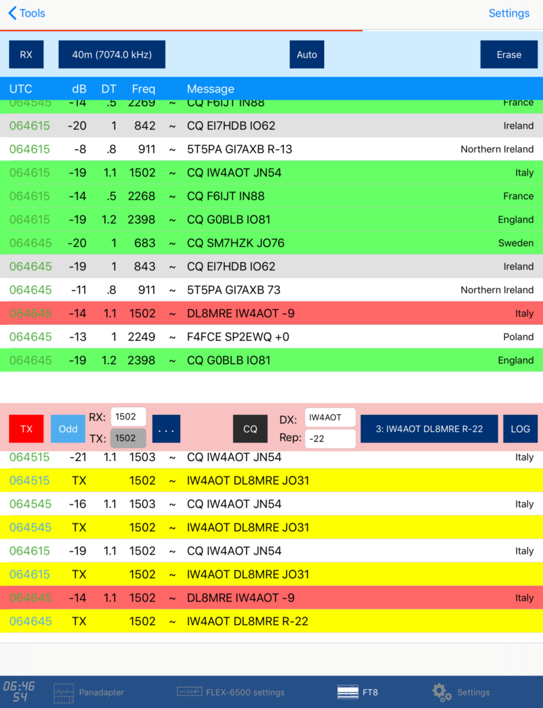
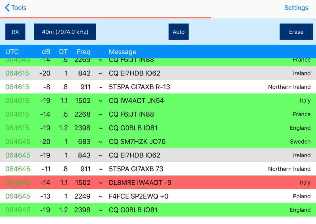
All received Messages are displayed in the list at the upper part of the screen. The following colors are being used:
- Green background: Somebody is calling CQ
- Gray background: You already worked that station
- Red background: your callsign appears in that message
Transmitting
The easiest way to start an FT8 QSO is by answering a CQ calling station.
Please note: Before answering a CQ call, ensure that the CQ button is turned off (gray).
Then, just double-tap a line of somebody calling CQ (yellow) in the upper receiving part of the screen.
Double tapping causes the following to happen:
- The frequency of the CQing station will be transferred to the RX entry field. If TX=RX is set (see more about this further below).
- The Callsign of the CQing station will be transferred to the DX entry field
- The dB report will be transferred to the Rep entry field
- If the CQing station is sending even (at second 0 or 30), the box next to the TX button will be changed to Odd or vice versa
- The TX button will be enabled (getting blue)
If you are fast enough (within the first 2 seconds), transmitting will start immediate because then, there are still chances that your answer can still be decoded. If you are too late, you will need to wait another 15-30 seconds, until you reach your next even or odd transmission phase.
If the AUTO button at the top is enabled (blue), the whole QSO will progress automatically until it’s finished. Read more about QSO Automation further below.
Instead of double-tapping a line, you can also single tap, which will do the same, except the TX button will not be enabled. This way, you can alter values such as the transmit frequency if you want and tap TX once you are ready.
Calling CQ
If you want to call CQ instead of answering CQ Calls, just hit the CQ button so that it turns blue.
Ensure that the first Message “1: CQ …” is selected in the Message selection and the desired frequency has been entered and decide whether you like to send CQ even or odd by using the button next to the TX button.
Next, tap on TX (make it blue) and transmissions starts on the next desired even or odd phase.
The TX list
The lower list, below the red transmit panel looks similar to the upper receiving list.
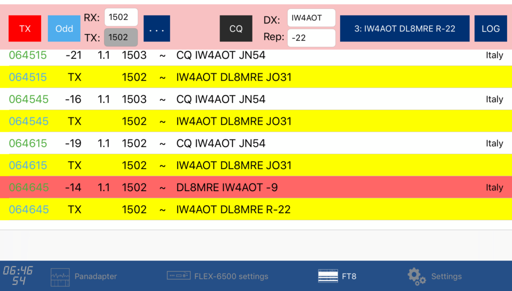
However, this list contains all your sent messages in yellow and marked with “TX” instead of a dB value.
In addition, it contains all messages that have been received on your RX frequency or messages that are containing your callsign.
This way, you can better focus on your QSO partner and will also see if somebody else is transmitting on the same frequency so you can interrupt your QSO or transmission.
QSO Automation
Because QSOs are standardized in FT8 (except for the two options to finish a QSO either by RRR or RR73), FT8 QSOs can be automated.
Whenever a message has been received, it the App knows which message needs to be sent next.
If you turn on the AUTO button at the top (make it blue), the App will automatically select the next message to be sent depending on the received message (even in case of an RRR or RR73) and sent the appropriate message automatically in the next transmission phase.
If you need more flexibility or want to finish a broken QSO, just turn off AUTO and select the message you like to be send.
If you select Message 9 {Individual}, you can even enter anything else as message which you would like to send.
TX and RX Frequency
Usually, you may want to transmit on the same frequency where your destination is transmitting. However, if there are many other stations trying to answer your destination, you may barely get heard. In this case, it’s better to send on another frequency. This is possible because for receiving, it simply doesn’t matter at which frequency the signal appears it needs to be at least in the FT8 frequency spectrum.
Keep in mind that a frequency, which appears to be clear for you, might be crowded for somebody else.
Using the […] button right from the two frequency entry fields, you can either enable or disable TX being equal to RX.
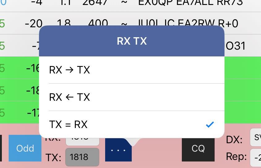
If there is a checkmark, the TX frequency will always be equal to the RX frequency and you can’t enter a different value. If you uncheck TX = RX, you can operate on a different TX frequency.
The RX -> TX option will move the current RX frequency to the TX frequency field. RX <- TX will do the opposite.
Clearing the Screen
After a while, or after finishing a QSO, you may want to clear the lists. Tapping once on the ERASE button at the top will clear the TX list. Tapping twice will clear both lists as well as the DX and Rep entry fields.
Logging QSOs
Whenever you tap on Log, a Logging screen will be displayed. This screen is prefilled with values that are already known (e.g. DX call, Report etc.).
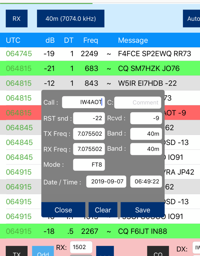
If Auto Logging is turned on (see Settings, further below), the Logging screen will appear automatically whenever a QSO has been finished (xx73 received).
Settings
There are just a few settings available because most of the otherwise mandatory Audio, CAT or Device settings are obsolete for this App and FlexRadio combination.
DAX Channel to use:
If you hit RX, the FT8 tool will always use the first slice. If there is no slice, it will be created. That slice will get DAX enabled on the DAX channel entered here. DAX channel 1 is the default and should work best for most scenarios.
A situation where you may want to use another channel could be, if you want to have a PC (or another App) connected to the same Radio and don’t want that connection to be interrupted when using FT8. In that case, create at least two slices. Use the second slice on a different DAX channel with your PC or another App.
Max. retries:
When calling CQ or answering a call, messages will be resent if there is no or no correct answer. To prevent infinite transmission attempts, you can limit the number of retries using this setting.
Mark worked before:
If you are using the internal Logbook feature of this App and if you are logging calls, messages in the top receiving list will be marked gray if they are already in your Logbook.
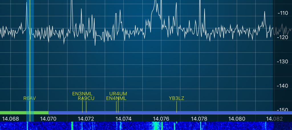
Show DX Calls on Panadapter:
Like DX Cluster Spots, FT8 CQ Calling stations can also be displayed on the Panadapter if this option is turned on. For details see further below.
Auto Log after QSO:
If switched on, you will be prompted automatically of a QSO has been finished to log that QSO to the Logbook.
FT8 CQ Calls on Panadapter
If switched on, CQ Calling stations on FT8 will be displayed on the Panadapter similar to the DX Cluster spots.
You will also see your Transmit and Receiving Frequencies as TX, RX (or RX/TX marker if you set RX equal to RX).
Please note, you can adjust the position of the Callsign from the Settings of the BandMap tool. A position of around 170 will display calls at a location where it doesn’t conflict with the FFT part on the panadapter so they will easier to be read.
Background Operation
You can switch between all screens (Panadapter, switch to other tools or Settings) without getting disconnected. This is even possible during an FT8 transmission phase.
This way, you can easily monitor the Frequency or your transmission on the Panadapter and head back to the FT8 list. Or you can check your Logbook or the DX Cluster.
It is even possible to leave this App and start another. However, when leaving the App, transmissions will be disabled until you re-open this App again.
Please note: In order to stay connected with your Radio when you leave the App, you need to have disabled the “Disconnect on close” setting on the Settings screen of this App.
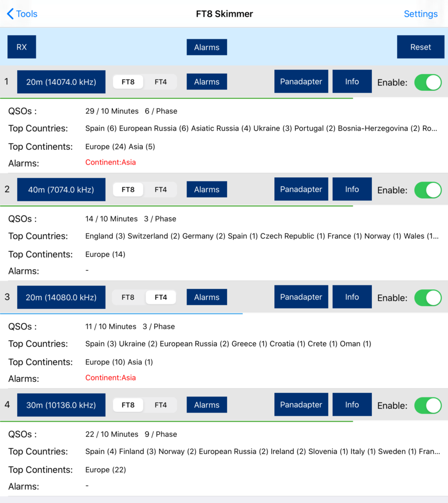
1.13.FT8 Skimmer
This Tool allows to monitor FT8 or FT4 activities on up to four Bands at the same time. This is useful, if you are waiting for good DX conditions or if you are interested in a certain DXCC or special call. You can let the App run, monitor the activities and let it ring on predefined alarm conditions.
PLEASE NOTE: If you like to let this tool running all the time, better switch “Disconnect on close” off and “Prevent device sleep” on. These settings can be found on the App Settings screen.
How to use
Once started, you will see four monitoring panels. Each with an enable switch on the right side. Each monitor can be set to monitor a certain band in a certain mode (FT8 or FT4).
After selecting the Band, mode and enabling the monitors you like to run, tap on the RX button at the top to start all enabled monitors.
Tapping the RX button again will stop monitoring.
Once the first FT8/FT4 phases have passed, you will see information about the activity on the selected band. The first line QSOs will give you an impression about how busy this band currently is by reporting the number of QSOs during a pre defined time frame (see settings below) or per Phase.
For monitoring, the first four (two on a FlexRadio 6400) panadapters will be allocated, each with a single Slice which will be tuned to the desired frequency. By tapping on Panadapter, the App jumps to the corresponding panadapter so you can watch the activity live on the waterfall.
PLEASE NOTE: If you leave this Tool by hitting the back button at the top, monitoring will be suspended. All allocated panadapters and slices will be released which allows you to directly open the FT8 Tool in order to work your desired station. This behavior is different to the FT8 Tool which will continue to run even if you close it.
Alarms
You can either set global alarm condition, which applies to all four monitors or alarms that only apply to a particular monitor (band). To set the alarms, either tap on the top Alarms button or the individual Alarm buttons inside each monitor.
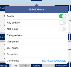
The enable button at the top can enable/disable this particular alarm. Any activity will ring the alarm in case of any station on this band. Not in log will ring an alarm if there is a station heard that is not yet in your log. The Calls/prefixed field can be used to add complete callsigns or just call prefixes that will caus an alarm to be rang in case those calls (or prefixes) have been heard. Multiple entries need to be separated by comma (,).
You can maintain ITU-Zones and CQ-Zones in a similar way.
Countries and Continents can be selected from a popup window that will open, once you tap on the entry.
Alarms will rang if one or more of the entered criteria match. In such an alarm case, you can see what has caused the alarm at the bottom line of each monitor colored in red.
Settings
In the Settings menu for this Tool, you can select the Monitoring duration. Calls older than this time will be discarded and not counted.
If you are only interested in Band activities of CQ calling stations, just switch “Monitor only CQ calling” on.
Beep on alarm can be switched off if you don’t want to hear the alarm sound.
1.14.Call lookup
The Call lookup Tool can be used to learn more about a certain call-sign.
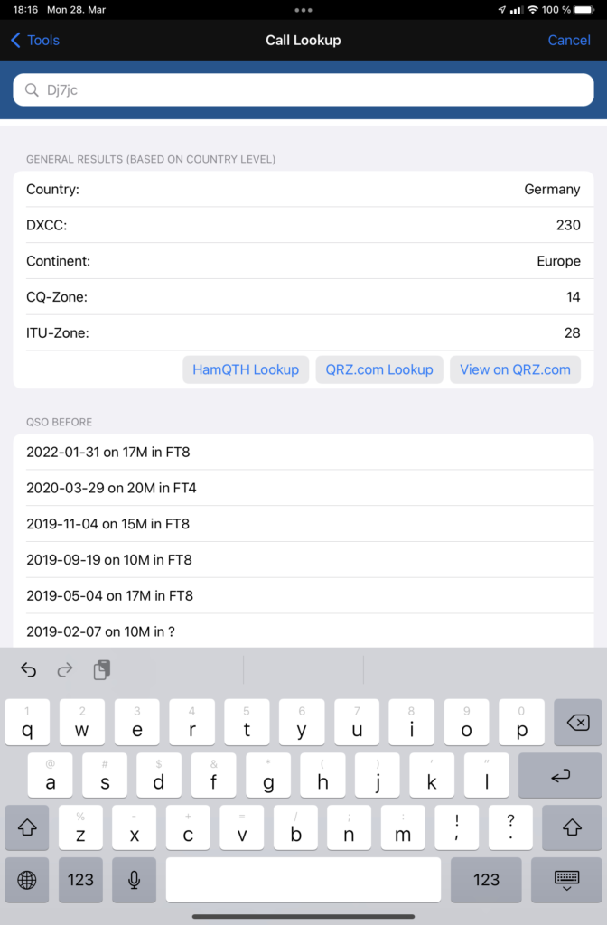
After entering the Call-sign in the top entry field, Basic information like Country, DXCC, CQ- and ITU-Zone will be displayed immediately. This information comes from an internal Database of the App which will be updated from time to time. This information is only accurate down to a country level. The location within a country will always be the location of the capital city of the country.
Further below you will get a list of previous QSOs to the entered Call-sign.
For more accurate and detailed information like the name, exact location or even Email address, you can use one of the integrated call lookup services like HamQTH or QRZ.com. If you have an account on one or both of these services, please enter your account information in the App Settings. In that case, you can use the HamQTH or QRZ.com lookup buttons for best results and most convenient display. If you don’t have accounts for these services, you can at least use the View on QRZ.com button which will show the QRZ.com website for the particular call-sign.

1.15.PSK Reporter
PSK Reporter is a great automatic propagation reporter for digital modes, including FT8 / FT4.
You can use PSK Reporter to get an almost instant idea about the current DX conditions and who is able to copy you around the world.
This App integrates PSK Reporter in two ways.
Submitting PSK Reporter spots
PSK Reporter lives from the fact that many HAMs are contributing their reception reports to PSK Reporter. This App can automatically send FT8 reports to PSK reporter when enabled (under Settings inside the FT8 Tool or the PSK Reporter Tool).
If enabled, a list of received FT8/FT4 signals will be submitted to PSK Reporter every five minutes. Except for the information about your antenna (which is optional), nothing else has to be configured.
Viewing PSK Reporter results
The opposite side of PSK Reporter is to view a list of all stations who received your signal. This is, what the PSK Reporter Tool is for.
To get a report of stations that are able to copy you, first have a QSO or a test transmission on a band you are interested in. Next open this Tool and enter your callsign at the top of the window (it not already per-filled) and click on the search button.
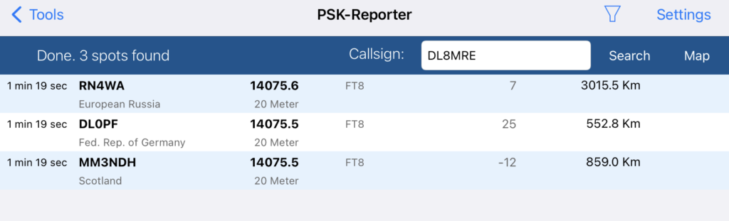
Once the list is filled with reports you can tap on a line for more details.
It may take up to 15 minutes after your transmission until you will see your results. This is because every contributing listener will update their reports every five minutes and it is not possible to download reports from PSK Reporter sooner than every 5 minutes as well. If you would request an update sooner than after five minutes, you will see an according message at the bottom of this window.
You can narrow down the results by using the Filter Icon at the top and selecting a Mode and Time.
You can also visualize all locations on a map by switching to the map mode using the Icon at the top.
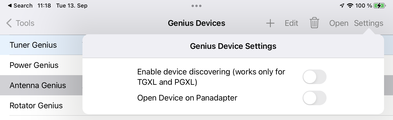
1.16.Genius Devices
FlexRadio and 4O3A are offering several network controlled accessories such as the Power Genius XL (PGXL), Tuner Genius (TGXL), Antenna Genius (AGXL) and Rotator Genius (RGXL) which can also be maintained from within the App.
PLEASE NOTE: This feature is only available for iPads
PLEASE ALSO NOTE:
This App requires the following Firmware versions for correct operation: PGXL: 3.7.x or 3.6.x, TGXL: 1.1.8, AGXL: 3.1.5 and RGXL: 1.5.0
If device discovering is enabled, PGXL and TGXL will automatically be discovered and displayed. AGXL and RGXL need to be added manually using the Add (+) button. Device discovering doesn’t work remotely.
Devices also need to be added manually the same way if you want to access them via remote access from outside your local network.
By double-clicking on a device in the list or selecting a device and clicking the open button, the App will connect to the device and open the device control screen.
The PGXL control screen
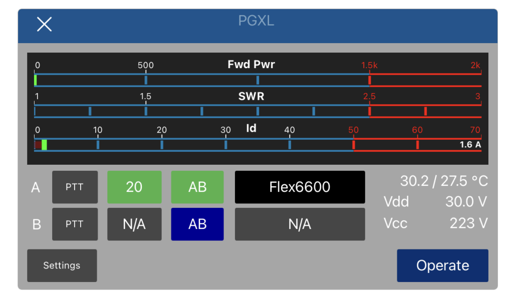
From here, you can monitor the operation of the PGXL and change the PGXL settings.
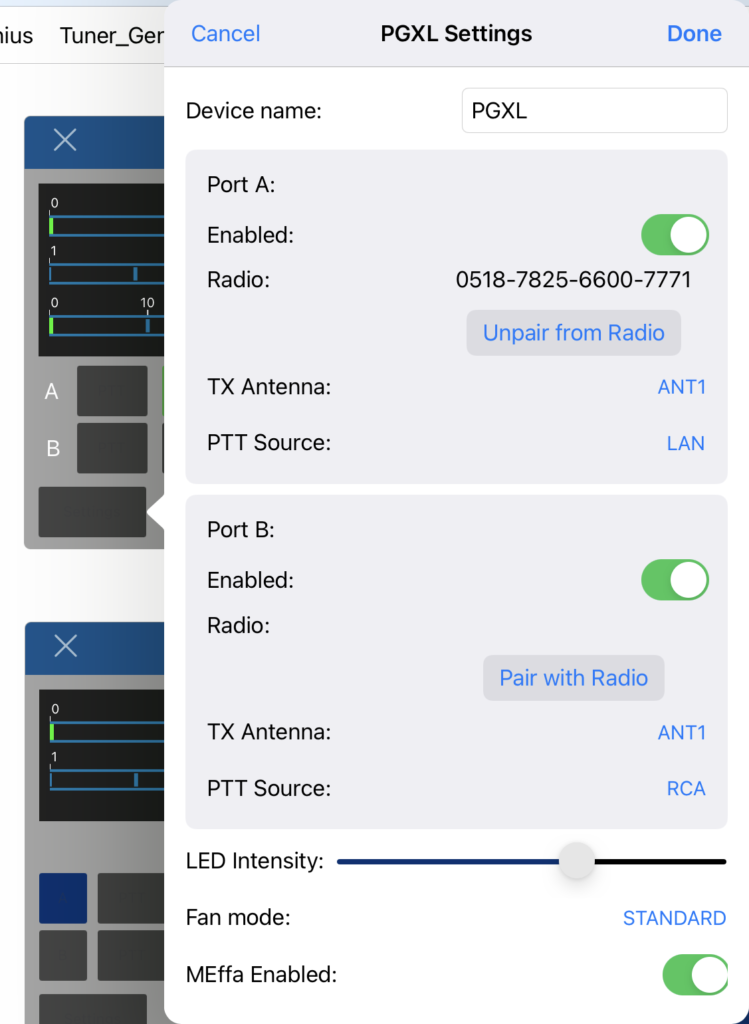
In order to use the PGXL along with your FlexRadio you need to pair one or both ports with your Radio. For this, you need to be connected to your PGXL and your Radio locally and click the “Pair with Radio” button.
The TGXL Control screen
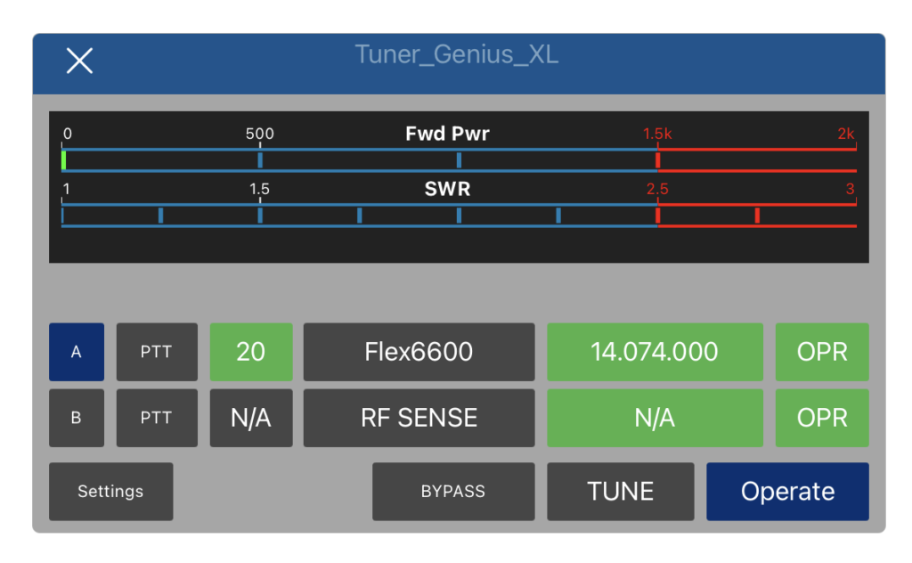
The TGXL control view has a similar layout like the PGXL control view and offers buttons for Tuning or setting the Tuner on Bypass.
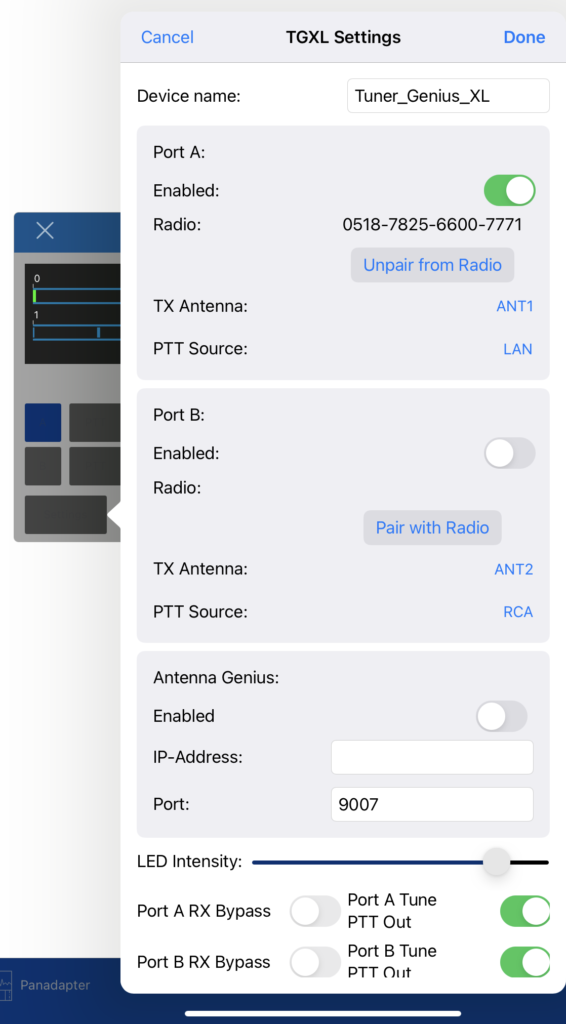
Also the TGXL settings screen looks similar to the PGXL settings screen. Also pairing the Radio with the TGXL works the same way by using the “Pair with Radio” button.
AGXL Control Screen
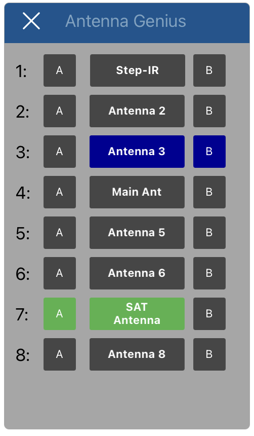
From here, you can assign port A or port B to one of the eight Antenna sockets of the AGXL.
RGXL Control Screen
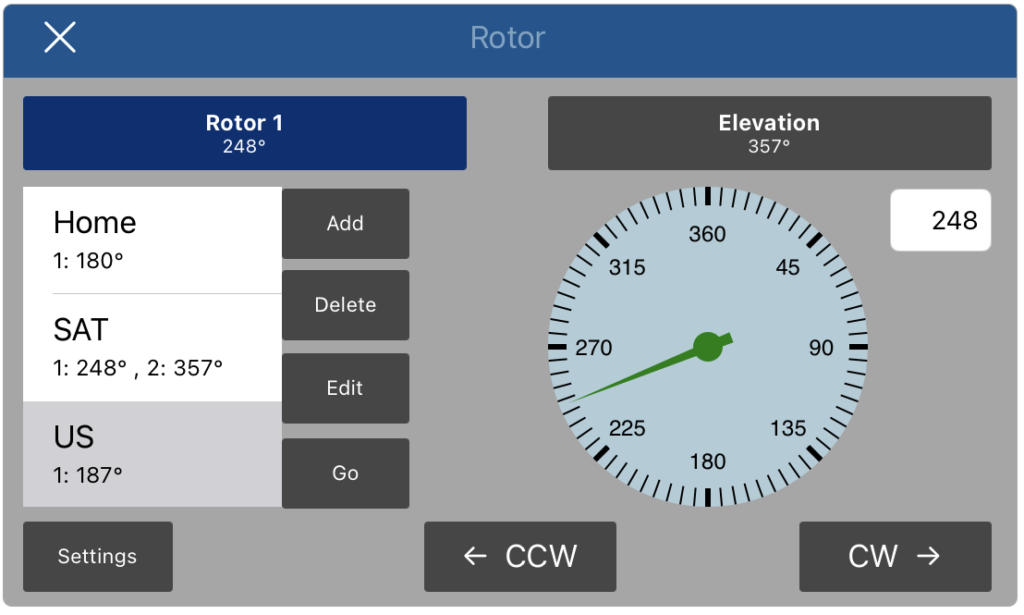
From here you can enter a certain rotor direction or rotate the rotor counter-clockwise or clockwise. On the left you can add presets for quick rotation to certain directions. Different to the Windows App, you can also enter predefined directions of a single, both together or both rotors individually if you have more than one rotor.
Hitting Settings will open the settings for the currently selected rotor where you can rename it and change limits and offset.
Different to the Windows App, you can also change the Rotor mode to Elevation.
Remote access
As mentioned earlier, if you want to access Genius devices remotely, they can’t be discovered and need to be added manually.
For this use the Add (+) button (or the Edit and Delete buttons to change or remove a device).
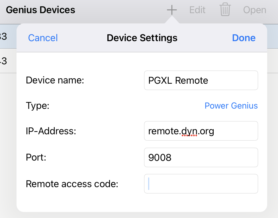
Here, you can enter the remote access Address that should be used to access your network where your genius device is located. For a TGXL you also have to enter a Remote access code which is identical to the Remote access code you can maintain in the local TGXL settings. The PGXL however, doesn’t provide this extra security measure.
Check or uncheck the “Is 3-Antenna Device” depending on whether or not you are using a SO2R version.
2.Appendix
2.1.iCloud Drive
iCloud Drive can be used for Im- and Export functions of the App as well as Logbook Synchronization.
iCloud Drive is a special feature of iCloud but not the same. You can use iCloud Drive even without using other iCloud features like Keychain Synchronization.
To use iCloud Drive, the following needs to be enabled:
- In your iPhone/iPad Settings: iCloud must be turned on
- Further below, there is a “iCloud Drive” setting which also needs to be turned on
On this screen AND under iCloud Drive there are additional switches for additional features for iCloud and iCloud drive. All of those are not necessary for the App. You only need iCloud in general and iCloud Drive switched on for SmartSDR.
- Inside the App, in the App Settings, you will also need to set “Enable iCloud Drive” to on. Below, the Status should say “Available” if your iCloud Settings are correct.
No Software installation is needed on a PC or Mac to use iCloud Drive as it can be used from any Browser like Safari, Internet Explorer, Firefox or Chrome.
However, if you prefer, you can install iTunes and the included iCloud Drive software from Apple on your PC or Mac. In this case, no Browser is needed. In that case, the iCloud Drive Folder will be replicated on your PC or Mac as virtual Directory.
For using your Browser to access iCloud Drive, you just need to visit the https://icloud.com website.
After entering your Apple ID and password you need to click on the iCloud Drive Icon and you should see the special SmartSDR folder like shown below:
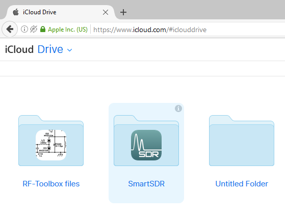
This folder contains all your SmartSDR Files after Exporting Files to iCloud Drive. For the opposite direction (e.g. if you like to import ADI Log files), just copy your File from the PC/Mac to this SmartSDR Folder by Drag-and-drop. After a short while (it may take a few seconds until your file has been synched to the Cloud) you will be able to select that file for importing in SmartSDR for iOS.
PLEASE NOTE: If this is the first time you use iCloud or iCloud Drive, it may take several Hours until you will see the SmartSDR folder. Once it is available, files will be transferred within a few seconds between your PC/Mac and the Cloud.
2.2.Mapping Editor
The Mapping Editor allows to assign Controls, Buttons and LEDs to individual FlexRadio functions.
You can start using this Editor in two different ways. You can either previously select a Default Mapping as described before, open the Mapping Editor and alter this Mapping according your requirements.
Alternatively, you can open the Editor and tap on the Trashcan (top right corner) to delete the whole Mapping and start with an empty list.
WHEELS/SLIDERS, BUTTONS and LEDS
The Mapping Editor Screen is separated in the three Sections WHEELS/SLIDERS, BUTTONS and LEDS.
Each section contains a code on the left side and the assigned FlexRadio action on the right side.
You can simply identify the code for a particular control by just using the control (e.g. hit a button or spin a wheel). The corresponding Code line for that control will then be highlighted in the list. Missing controls will be added this way automatically.
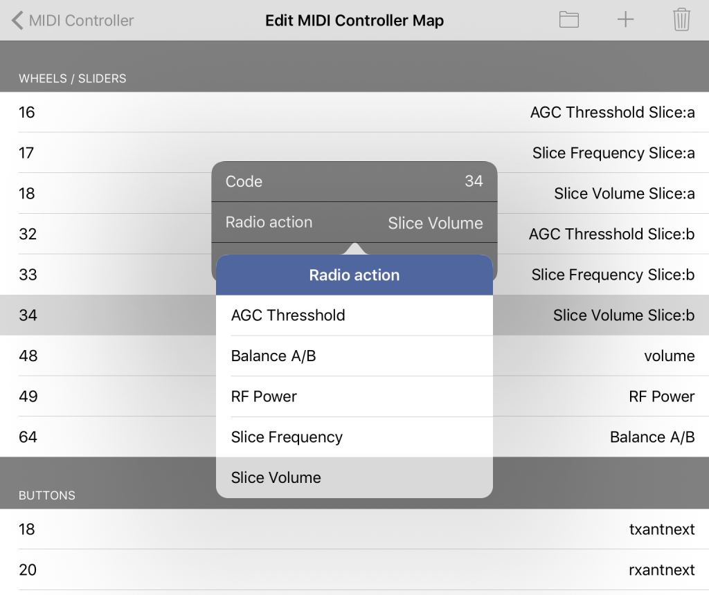
To assign a new or alter a FlexRadio action for a control, just tap on the corresponding line.
Depending on the Section (and type of Control), you can select different Actions. For example, a Wheel can be assigned to change the Slice Frequency which makes no sense for a Button. A Button on the other hand can be assigned to Start Macro 1 for example which makes no sense for a Wheel.
You will see a small screen which asks for two or three parameters as follows:
1. The Code.
This is the Code, send from the Controller for the particular Control. Even though it’s possible to enter this code manually, it is more convenient to identify the codes as mentioned before by just using the Control on the Controller.
2. Radio action
This is the function you want to control on your FlexRadio (for instance the Frequency, the PTT or a Macro which should be sent).
Most of the FlexRadio actions are self-explanatory as they are one-by-one identical to FlexRadio functions.
One exception is the Balance A/B action which has no direct FlexRadio counterpart. What this action does is basically to adjust Alice A and B volume. When spinning the Wheel (or moving a slider) to the left (counter clockwise), volume of Slice A will be increased and B decreased. When spinning (or sliding) to the other direction, volume of Slice A will be decreased and for Slice B increased.
For a fill list of available acrtions, please refer to the Controller Actions Table in Appendix of this Manual.
3. Slice (Optional)
Some Radio actions require an additional Slice Parameter which can be selected here.
IMPORT/ EXPORT
By using the Folder Icon at the top, you can export or import individual Mappings (or Backups while trying out different Mapping options). This way, you can even Export and Import your Settings to another Device or share Settings with another OM.
In order to use this Import/Export feature, you need to have iCloud Drive enabled on your Device as all files will be stored on a separate SmartSDR Folder on iCloud Drive (for more information see the separate Chapter “iCloud Drive” further below)
2.3.Controller Actions
In the three tables below, you can find all available actions which can be assigned to Controls by using the Mapping Editor.
Wheel and Slider Mappings:
| Name | Slice Parameter | Description |
| Slice Frequency | a-h,tx or active | Changes the frequency of the given Slice |
| Slice Volume | a-h,tx or active | Changes the AF-Gain of the given Slice |
| AGC Threshold | a-h,tx or active | Changes the AGC-Threshold of the given Slice |
| RF Power | Changes the RF Power | |
| Balance A/B | Controls volume balance between Slice A and B |
Button Mappings:
| Name | Slice Parameter | Description |
| Slice new | Creates a new Slice | |
| Slice next | Selects and activates the next Slice | |
| Slice set active | a-h or tx | Activate given Slice |
| Slice set TX | a-h or active | Set given Slice to TX Mode |
| Slice Lock | a-h,tx or active | Lock the given Slice |
| Mode Next | a-h,tx or active | Switch to next mode for given Slice |
| Mode USB | a-h,tx or active | Set Mode of given Slice to USB |
| Mode LSB | a-h,tx or active | Set Mode of given Slice to LSB |
| Mode CW | a-h,tx or active | Set Mode of given Slice to CW |
| Mode AM | a-h,tx or active | Set Mode of given Slice to AM |
| Mode DIGL | a-h,tx or active | Set Mode of given Slice to DIGL |
| Mode DIGU | a-h,tx or active | Set Mode of given Slice to DIGU |
| Mode AM | a-h,tx or active | Set Mode of given Slice to AM |
| Mode FM | a-h,tx or active | Set Mode of given Slice to FM |
| Mode RTTY | a-h,tx or active | Set Mode of given Slice to RTTY |
| PTT Push | a-h,tx or active | Sets given Slice to TX mode and activates/deactivates PTT |
| PTT Toggle | a-h,tx or active | Sets given Slice to TX mode and toggles PTT |
| TX Ant 1 | a-h,tx or active | Set ANT1 as TX Antenna for given Slice |
| TX Ant 2 | a-h,tx or active | Set ANT2 as TX Antenna for given Slice |
| TX XVTR | a-h,tx or active | Set Transverter as TX Antenna for given Slice |
| RX Ant 1 | a-h,tx or active | Set ANT1 as RX Antenna for given Slice |
| RX Ant 2 | a-h,tx or active | Set ANT2 as RX Antenna for given Slice |
| RX RX_A | a-h,tx or active | Set RX_A as RX Antenna for given Slice |
| RX XVTR | a-h,tx or active | Set Transverter as RX Antenna for given Slice |
| RIT | a-h,tx or active | Toggle RIT for given Slice |
| XIT | a-h,tx or active | Toggle XIT for given Slice |
| VOX | Toggle VOX | |
| ATU | Start Tuning | |
| Tune | Toggle Tune | |
| Bypass | Set Tuner to Bypass | |
| MOX | Toggle MOX | |
| MEM | Toggle Tuner MEM | |
| NB | Toggle NB | |
| NR | Toggle NR | |
| ANF | Toggle ANF | |
| CWX | Opens CWX Window | |
| ANF | Toggle ANF |
LED Mappings:
| Name | Slice Parameter | Description |
| MOX | LED on when MOX on | |
| TX On | a-h or active | LED on when particular Slice is in TX mode |
| Slice Active | a-h or tx | LED on when particular Slice selected |
| Tune | LED on when TUNE on |